Advanced Structural Engineering Solutions
The FORUM8 software catalogue includes a wide range of specialist tools for advanced structural engineering design and behavioural analysis in major infrastructure projects such as bridges and tunnels. These are available as standalone products or as extensions to the VR-Design Studio simulation and modelling software.
 Ver.11
FORUM8’s flagship product, Engineer’s Studio® is 3D structural analysis software for the determination of the non-linear behaviour of structures using continuous plate element analysis. Designed to meet the latest civil engineering standards for the construction of bridges and highways, Engineer’s Studio® enables shear strength and curvature verification as a test for the dynamic analysis on structures including material specifications related to load bearing, resilience and seismic influences.
A modular software system, Engineer’s Studio® is widely used by engineers working in some of the world’s earthquake-prone regions to define structures, materials, and loads for planar and spatial structural systems consisting of plates, walls, shells. With an extensive range of plugin modules available, Engineer’s Studio® enables structural engineers to create designs for combined structures as well as model solid and contact elements for large-scale buildings, bridges and tunnels capable of withstanding extreme seismic activity.
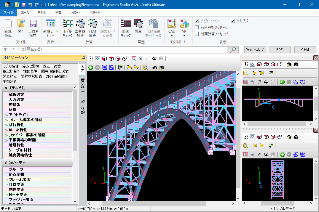
▲Main screen
Key Functions
Analysis Features
Main feature in analysis is that implement the 3D filer elements, which have ever received a good reputation and many actual results in UC-win/FRAME(3D) and the plate elements based on the Reissner-Mindlin theory and also static / dynamic analysis are available, considering material nonlinearity and geometric nonlinearity(Large Displacement) simultaneously.
Plate elements can have laminated structures, consists of layers which direct to the thickness way and define each setting for different type of materials between each layers or linear/non/linearity. Reinforcement concrete non linear constitutive equation is adopted as concrete constitutive equation applied to the plate elements, which was developed by the concrete laboratory in Tokyo University. It can be said that this product’s plate element has expanded RC element in UC-win / WCOMD to thickness way to multi-layer and has made it possible to analyze non-linear behavior not only of in-plane deformation but also of out-of-plane.
The isoparametric elements that are often used in the FEM have been adopted as flat plate elements.
Addition of a triangle primary element enables a mixture of 3 and 4 node elements during the automatic mesh of complex shaped field (refer to the Triangular Liner in the figure below). High mesh elements (quadrilateral 8 node element and triangular 6 node element) can be converted into low-elements (quadrilateral 4 node element and triangular 3 node element) after being selected.
・Triangular 3 nodes element and a primary form function
・Triangular 6 node element and a secondary form function
・Quadrilateral 4 node element and a primary form function
・Quadrilateral 8 node element and a secondary form function
The support of the 64bit version has realized the input and analysis of large models consuming a lot of memory.
You can output a report consisting of many pages (e.g. 30,000 pages).
Main analysis functions
Analysis
static analysis / dynamic analysis / eigenvalue analysis / analysis on the influence line of single bar
Nonlinear Analysis
material nonlinearity / geometric nonlinearity(large displacement) / composite nonlinearity
considering both material nonlinearity and geometric nonlinearity at the same time
Applied Theories
infinitesimal displacement / large displacement / elastic foundation beam theory /
Euler-Bernoulli beam theory / Timoshenko beam theory(considering shear deformation) /
Reissner-Mindlin theory
Elements
elastic beam element / rigid body element / spring element / M-φ element / fiber element /
plate element(laminated plate) / cable element / damping element (Speedy damper)
Boundary Conditions
locking condition: six degree of freedom for the nodal point(free or fixed or spring) /
distributed spring for elastoplastic beam element (two way of axial member direction and axial member) / Coupling spring (Defined at node)
Material Types
concrete / reinforcement bar / PC steel (steel strand wire, steel pipe) / steel plate / carbon fiber sheet / aramid fiber / elastic material(by input any young module) / non structural material(considering only weight per unit volume)
Definable Load
To frame element
nodal load / material load(concentrated / distributed / projection) / thermal load / forced load
To plate element
Flat plate surface load (Distributed load) / Flat plate volume force (Force acting in proportion to mass)
Plate ground displacement (Cylinder tank is the target. Loading of ground response displacement with load)
Flat plate hydrodynamic pressure (Subject to cylindrical water tank. Hausner’s approximate expression)
To cable element
Distributed load (Load distributed over cable length) / temperature load
Auto Created Load
dead load / prestressed load / horizontal seismic coefficient load
Static Load
monotone increasing / cyclic (constant, increasing) / reversible cyclic (constant, increasing)
Dynamic Load
acceleration wave( individual or simultaneous input of two components, vertical adn horizontal)
Dynamic Analysis
direct integration method by the Newmark-β method(β=1/4)
Damping
stiffness proportional pattern by element / Rayleigh damping / Rayleigh damping by element / (initial stiffness, instantaneous stiffness)
Mass Matrix
Consistent mass matrix / Lumped mass matrix
Input waveform is displayed on the result of the dynamic analysis
The seismic waveform you entered can be displayed in the new screen when you check the time history results of the dynamic analysis. Click in the graph to move to the next step, and the deformation figure and the section force are synchronized with the step.
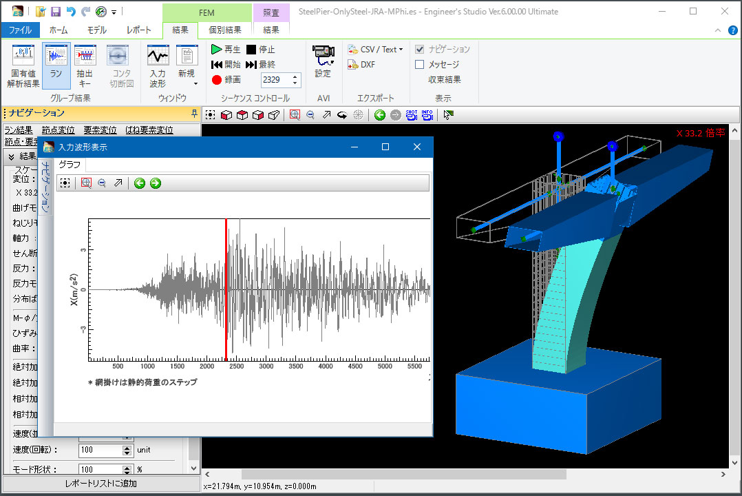
▲Entered waveform displayed on the history result
Non linear features
Following verifications to RC section compliant with specifications for highway bridges are available; allowable moment stress vrf, moment strength vrf, average shear stress vrf, shear strength vrf, minimum amount of reinforcing bar vrf.
M-φ feature
* Framework: bilinear (symmetric, asymmetric) / tri-linear (symmetric, asymmetric) / tetra linear (symmetric, asymmetric)
* Internal history: Normal / Takeda / elastic / origin-oriented / origin maximum point-oriented / H11 railway seismic
Spring feature
* Framework: bilinear (symmetric, asymmetric) / tri-linear (symmetric, asymmetric) / tetra linear (symmetric, asymmetric) / Nagoya high-speed rubber bearing type / BMR damper
* Internal history: Normal / Takeda / elastic / origin-oriented / origin maximum point-oriented / H11 railway seismic / positive and negative direction / positive direction / negative direction / shock absorber / Clough/slip type / Gap/Hook type
Hysteresis (stress-strain curve for the fiber element)
* Concrete
Quadratic curve / Hoshikuma / COM3 / JSCE / Mander
* Reinforcing Bar / Steel Plate / PC steel
frameworks:
Bilinear (symmetric, asymmetric)
Trilinear (symmetric, asymmetric)
* Carbon Fiber / Aramid Fiber
frameworks:Linear (tensile side only)
Fiber elements
Fiber elements(original): Non-linear elements using rigid body link and distributed spring elements. Effects of shear deformation will be ignored. Deformation and rigidity of the member at both ends are independent, and it is suitable to analyze the members that produce negative rigidity. In addition, because of the rigidity matrix based on the constant curvature assumptions up to half of the length of the element, it is also easy to adjust with plastic hinge etc. assumptions that assume curvature constant section such as road bridge.
Fiber elements(primary): Two nodes isoparametric elements using a primary curve for shape function. Based on Timoshenko beam theory, it considers shear deformation effects. Elements curvature distribution in the length direction is constant. Based on the rigidity evaluation on one of the Gauss integration point in the middle of member, it uses Gauss integration and builds rigidity matrix of element.
Fiber elements(secondary): Three nodes isoparametric elements using quadratic curve for shape function.
Convergent improvement and damage index of nonlinear flat plate elements
As a verification function for non-linear RC plate element, the program calculates the second invariant of deviation strain and the normalized cumulative strain energy that are the damage index written in “Concrete standard specification (2012, 2017)” by Japan Society of Civil Engineers. Also, the convergence setting for non-linear plate element has been added and the issue that non-linear plate element was not converged easily has been solved. This allows users to reproduce the softening phenomenon that occurs after the maximum peak in the load displacement relationship easier.
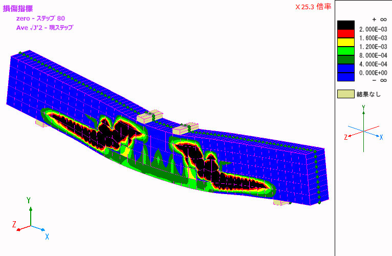
▲The second invariant of deviation strain of RC non-linear beam(average weight)
Design Support
* fiber elements, M-φ element, damage display of spring element
* display of damage on M-φ element
* display of damage on spring element
* stress calculation (mainly specifications for highway bridges)
* strength calculation (mainly specifications for highway bridges)
* curvature verification / spring element verification
* function of road bridge residual displacement verification
* ductility factor verification for highway bridges (μ=δmax / δy、μa=δls2 / (α*δy))
* displacement verification of highway bridges
* mport or export of CAD data(DXF / DWG format)
* IFC export
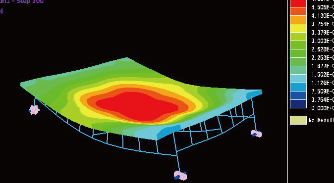
▲Displacement figure contour
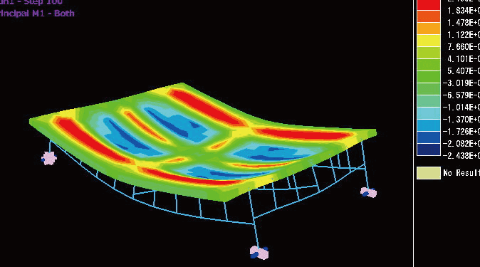
▲Slab bending moment contour
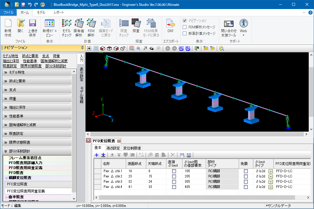
Civil Structure Biaxial Section Calculation (Partial Factors Method / Specification for Highway Bridges, 2017) Option
Verification by the partial coefficient method adopted in the Specifications for Highway Bridges, 2017.
As a verification for the dynamic analysis of structure, it is possible to perform the shear strength verification and the curvature verification against the maximum response value. Displacement verification and residual displacement verification are available for single column type RC pier and single column type steel pier at every step. In addition, the verification corresponding to the biaxial bending is supported for the displacement verification and residual displacement verification.
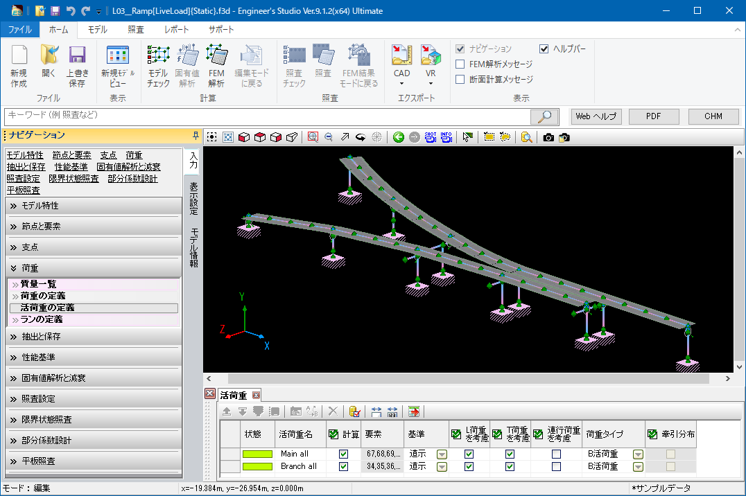
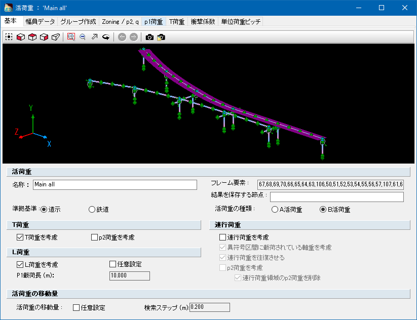
Calculation of live load
Live-load calculation is an analysis performed on the influence line of single bar. After creating the influence line, the program searches the location on each target point in which the section force etc. is the greatest or the least by moving the live-load (L load, T load and joint running interval). The analysis is usually for bridge axis.
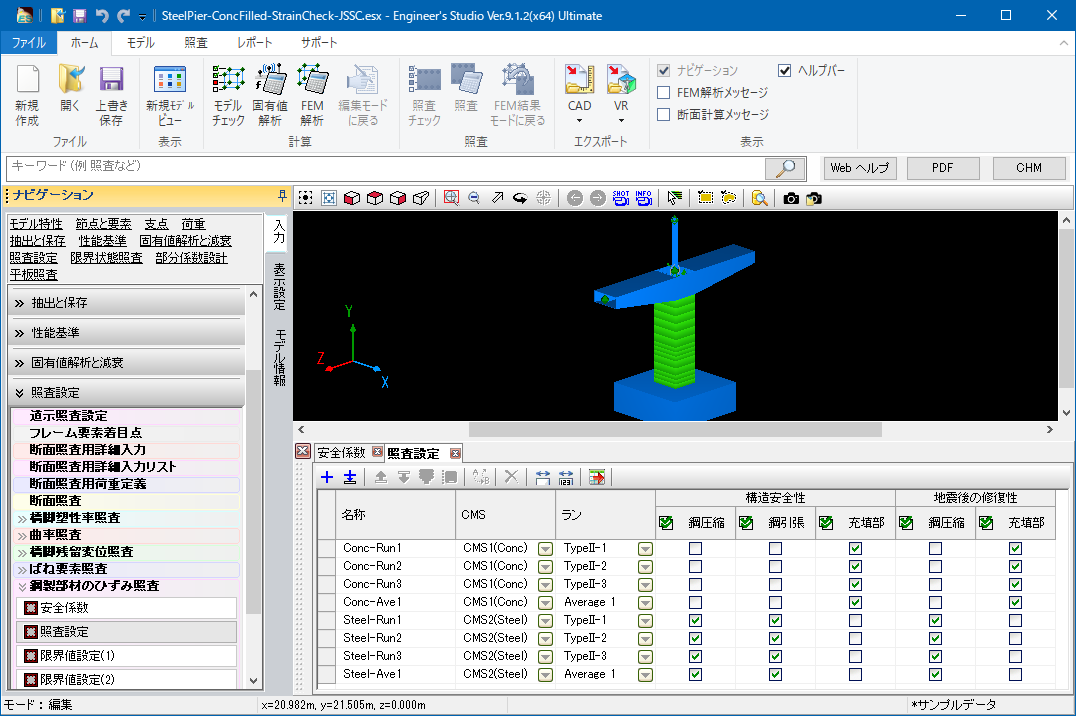
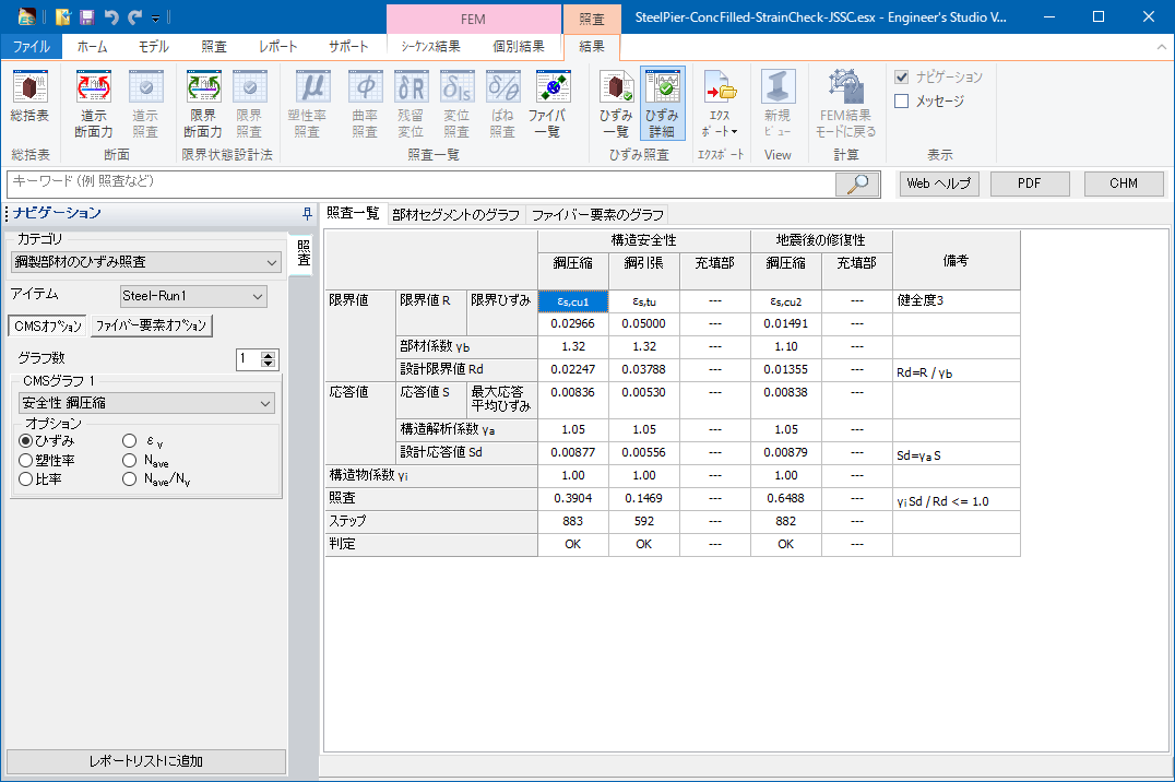
Strain check for steel members
Strain check based on the “Standard Specifications for Steel and Composite Structures” (February 2008, Japan Society of Civil Engineers) can be done. By modeling steel members using fiber elements and then assigning safety factors and ultimate strain, the result of strain check can be obtained.
Display NG materials in red
Elements (frame / spring) determined as NG in verification can be displayed in red in model drawings.
This function is available for the verification results of section, limit state, curvature, plasticity rate, displacement, residual displacement, and spring.
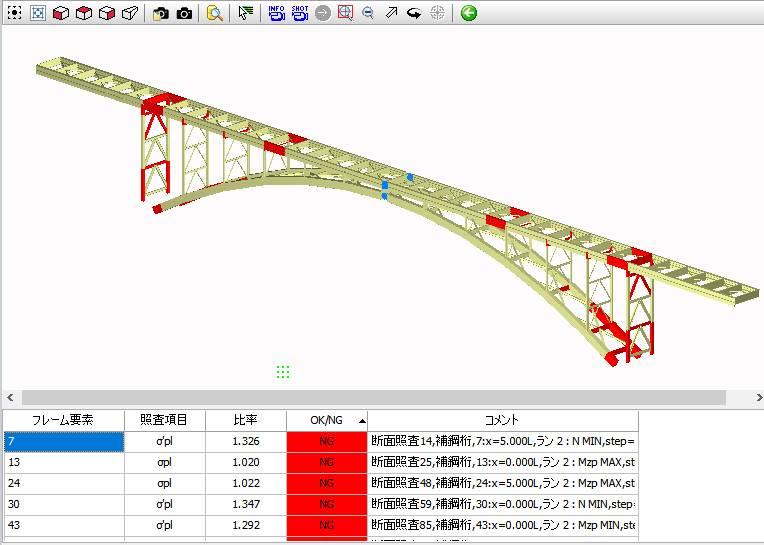
▲NG materials displayed in red
Request a FREE Trial
Seismic Analysis Tools
(GeoFEAS®) 3D – 3D Geotechnical Finite element Elasto-plastic Analysis Software.
(GEO FEAS®)3D analyses stress-deformation of soil under static conditions and is designed for 2D geotechnical analysis (including axial symmetric analysis) used widely in areas with high earthquake activity.
(GEO FEAS®) 3D is a joint development by FORUM8 and Ukai laboratory incorporating the ground analysis program developed by Ukai laboratory, Department of Civil and Environmental Engineering of Gunma University and the FORUM8 Pre-Post processor.
Read more
UWLC® – Dynamic effective ground stress analysis Software
This program analyses dynamic land transformation using finite element method (FEM). Taking into consideration the method of elastic theory based on effective stress, excessive pore water pressure which occurs during earthquakes and the declining of stiffness of the ground soils, it is possible to calculate land transformation by the hour. This program can be applied to investigating the stability of earth structures (banks or raised mounds), the lift of underground structures, and the dynamic interrelation between an earthquake and structures.
The analytic core of this program makes use of the land analysis program by Professor Ugai and his research laboratory at Gunma University. It is jointly developed by FORUM8 which is engaged in the development of the pre/post element of the solution.
Applications
FORUM8's advanced structural engineering software is used throughout the world in the design, planning and construction of major infrastructure projects. Using the latest analysis techniques engineers are provided with all the tools they need to ensure that their buildings and structures are designed to the highest standards taking into consideration the ground conditions, materials and building methodologies.
